Working with “wireless” LEDs feels a bit like magic. These tiny LED assemblies can emit light without directly connecting to a power supply. The secret to their energy source is a nearby wire coil in which a high-frequency oscillating current generates a fluctuating magnetic field. Each induction-powered LED is attached to its own tiny wire coil, which responds to this changing magnetic field by producing a small (about 2mA) current.
A Little Light Self-Reflection
I often obsess over finding novel ways to use LEDs in projects, such as my weather displaying edge-lit rainbow (build it at here) and Twitter-connected LED matrix handbag. I had impulsively purchased a set of 10 wireless LEDs in mixed colors and a 5V transmitting coil, hoping to generate new project possibilities from this unique LED form factor. Disappointingly, an online search produced numerous articles on how to build your own induction-powered LEDs, but very few examples of ways to use them!
Any project using induction-powered LEDs will be subject to some constraints. Power transfer between the 5V transmitter and the LEDs drops off dramatically over distances larger than a few centimeters, so the coil must remain close to the LEDs. Also, inductive power transmission works best if the receiving and transmitting coils are oriented parallel to each other; this limits the ways in which the LEDs can move while remaining illuminated (see Lee Wilkins’ “Inductive Adornments” in Make: Volume 81, and “Skill Builder: Induction Instruction” and “Inductive Charging Bag,” both in Volume 41].
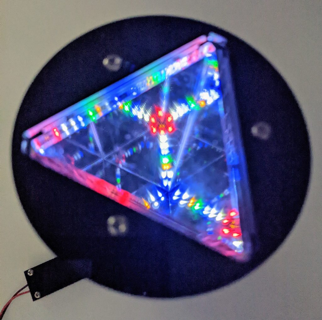
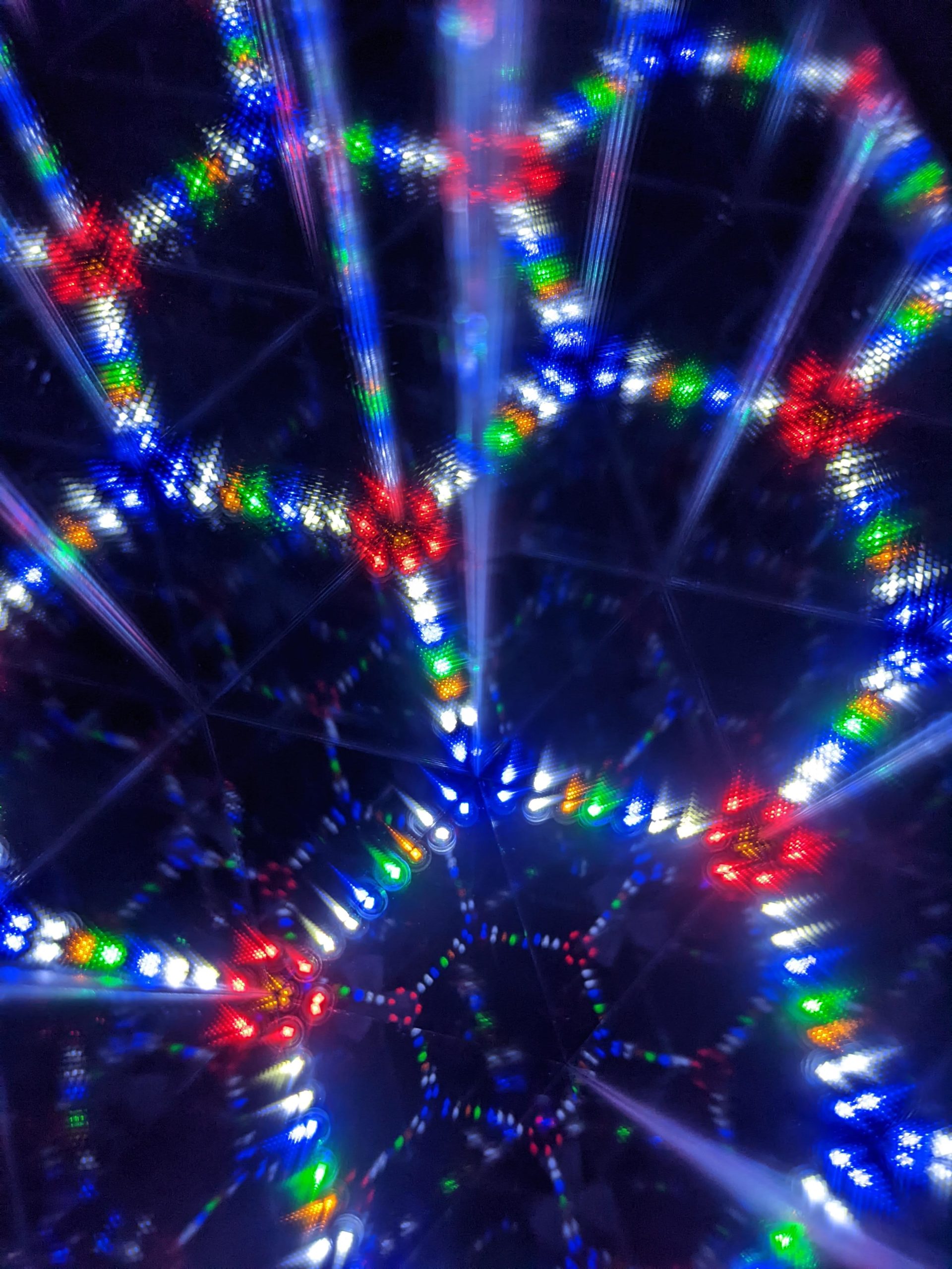
With these restrictions in mind, I wondered how wireless LEDs would look inside a kaleidoscope. The idea was compelling because a small number of colorful lights could create a large visual impact through repeated reflections in the kaleidoscope’s symmetrically placed mirrors. Induction-powered LEDs are particularly well suited for this use because they’re free to slide around when the kaleidoscope is moved, generating dynamic patterns with their shifting configurations. Encouraged by the possibilities, I designed and built this laser-cut kaleidoscope that uses wireless LEDs to generate colorful illuminated patterns. You can create your own version of the build from the instructions that follow.


 ). After you’ve cut the parts, remove the protective paper from every piece except the three mirrors.
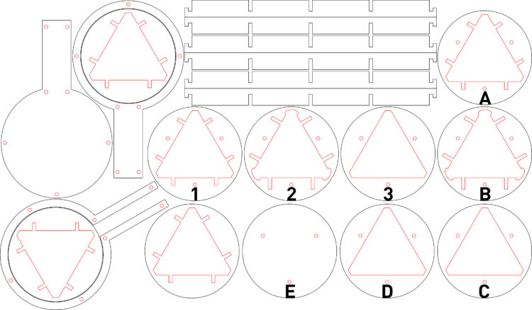
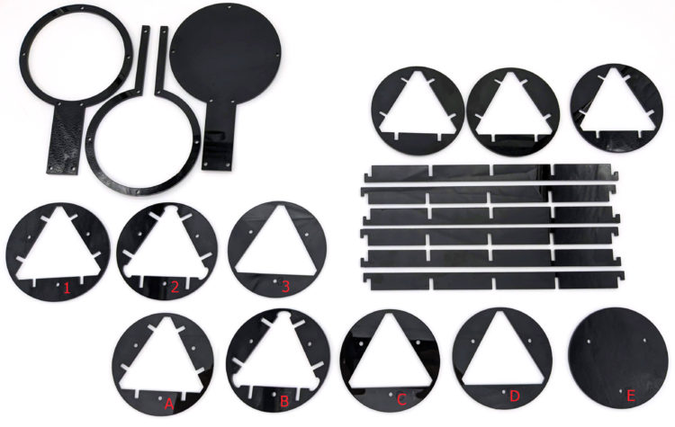
 ). Select the six identical notched brace pieces and the three circular pieces without screw holes. Connect the three center notches in each brace piece to a notch in each of the three circles. After slotting each brace piece into all three rings, tape it in position with painters’ tape to prevent it slipping out. (Figure C
 ). Be sure the brace pieces are seated as close to the outside edge of the circles as possible.
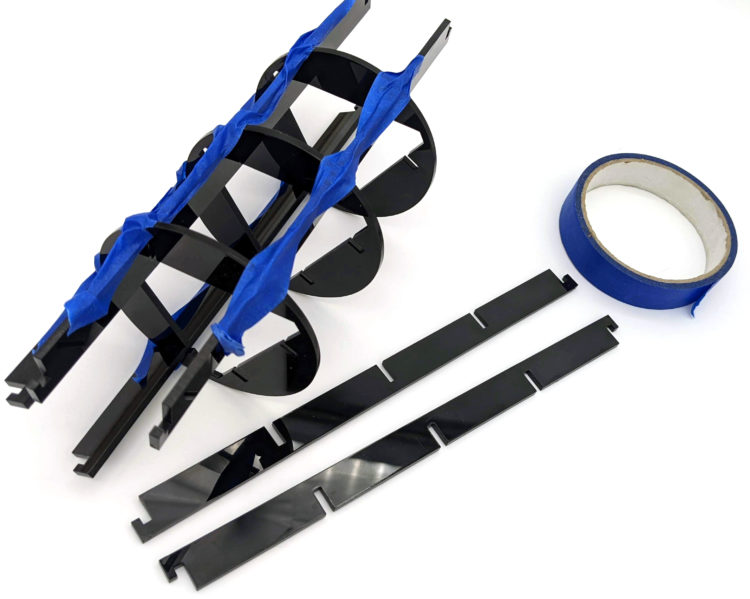
 ).
).
 E).
E).
 ).
).
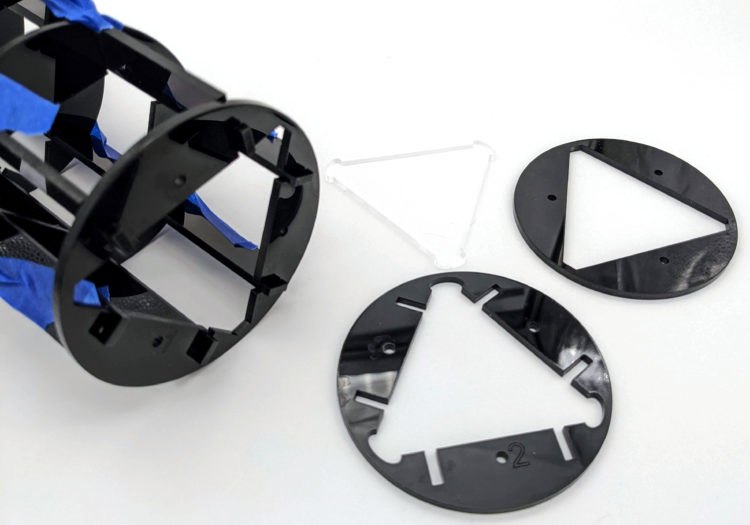
 ). Then set the partially assembled frame aside and gather the three rectangular mirror pieces.
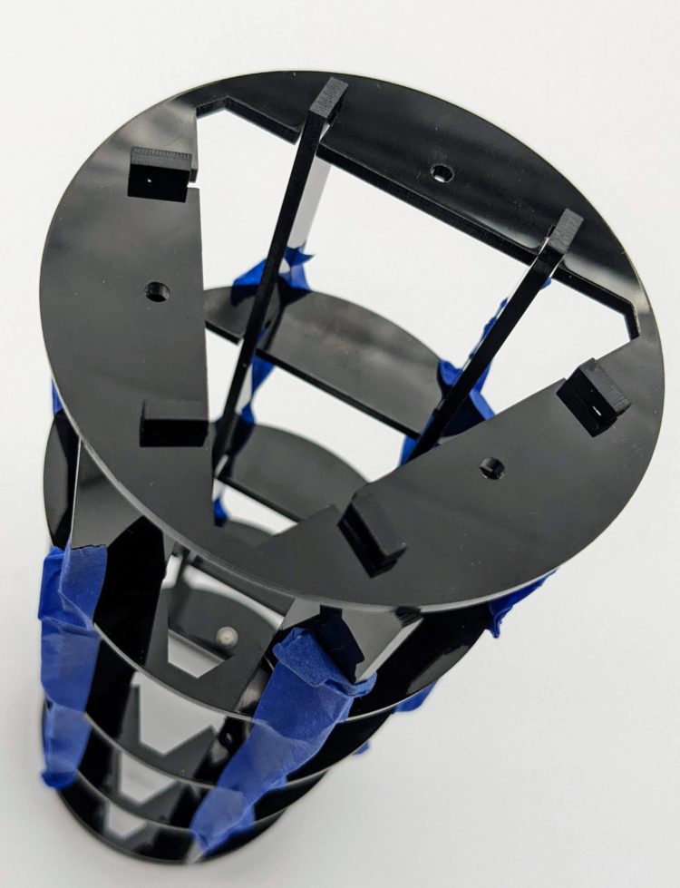
 H). There are a wide variety of decorative adhesive vinyl options to choose at most craft stores. While applying the vinyl, leave the protective paper on the mirrors’ reflective surfaces until you’re done, to avoid accidentally smudging or scratching the mirrors.
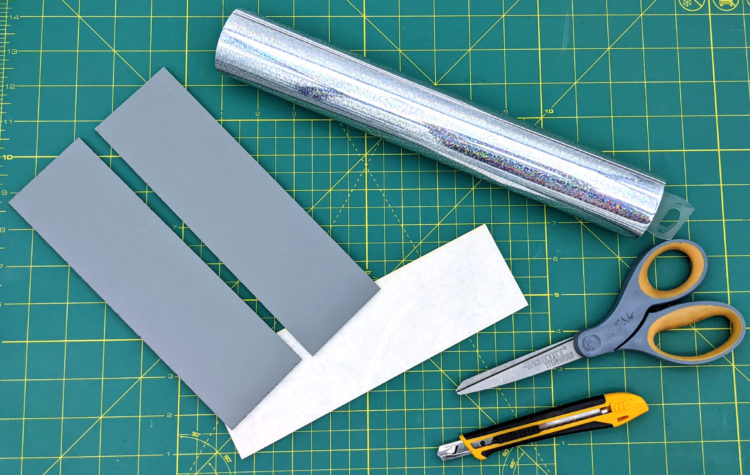
 ). Repeat this process for the other two mirrors.
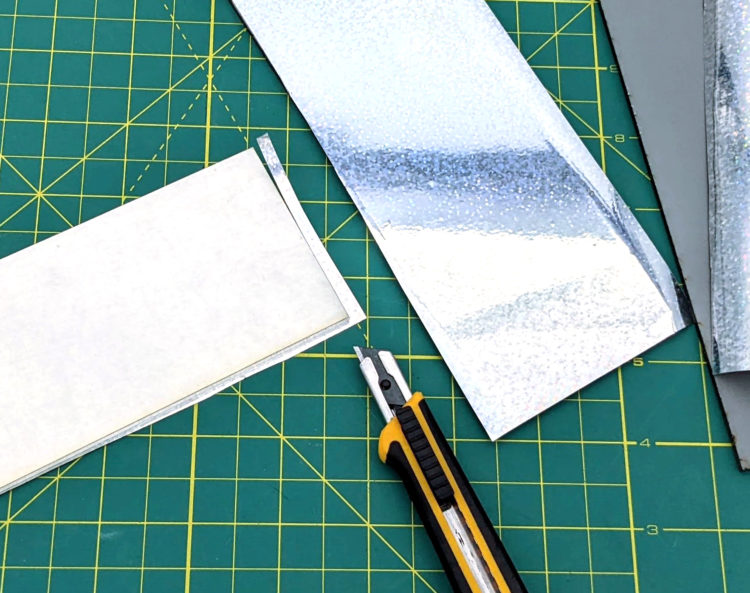
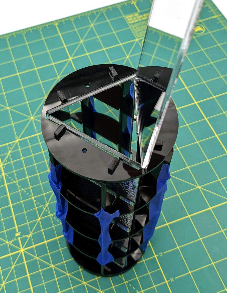
 J), and then turn the frame vertically before sliding the last two mirrors into place (Figure K
 ). If a mirror “catches” on the frame during this step, tug each of the long brace pieces toward the outside of the frame to create a bit more room inside the frame.
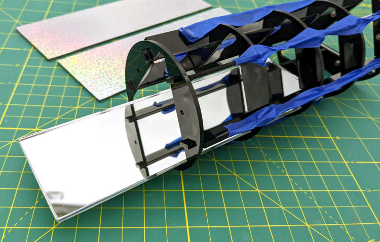
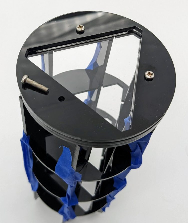
 ) and insert the three long (16mm) M3 screws and nuts into the holes. Fasten the nuts loosely for now, as we’ll remove them later to add the LEDs and their container to the frame. Remove the painter’s tape from the frame and discard it.
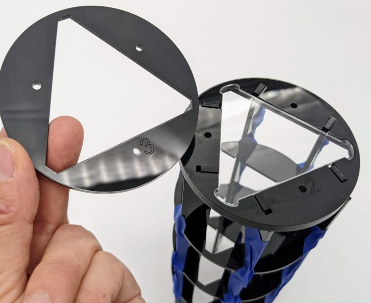
 M) acquire new dimensions inside a kaleidoscope.
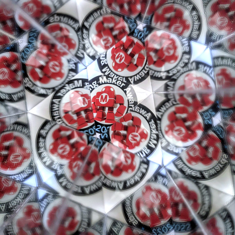
 . We’ll use the same holographic vinyl that covers the mirrors to secure the transmitting coil to its case.
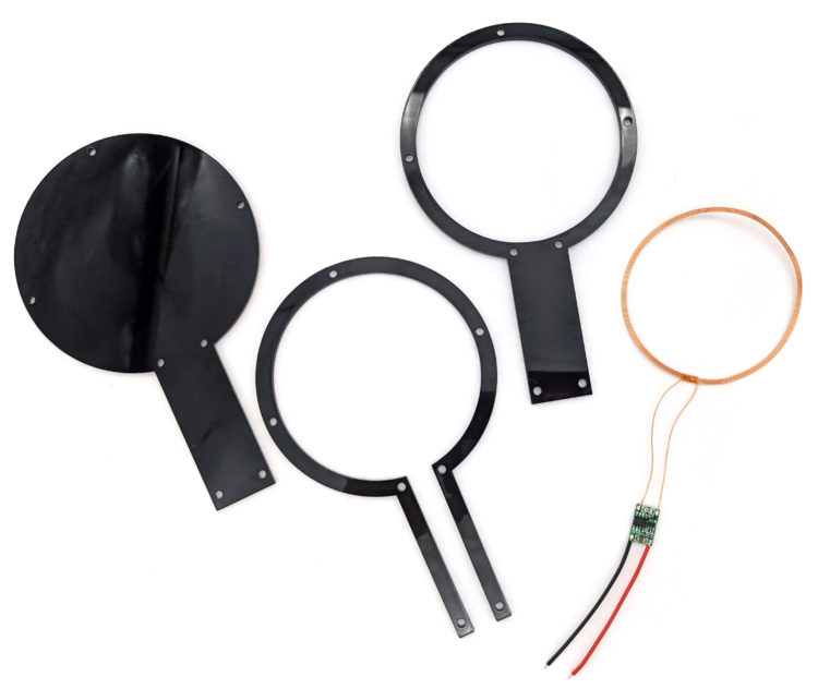
 ). Now turn the vinyl and coil over together and adhere them to the bottom layer of the transmitting coil case (Figure
  P). Trim away any vinyl that covers the current driving PCB or the screw holes in the case. Place the next case layer, which has the open slot in its handle, on top of the vinyl, then place the final, solid-handled layer on top of that one. Secure the three case layers together with five M3×12mm screws and nuts. The transmitting coil’s power wires will extend from the end of the case’s handle (Figure Q
 ).
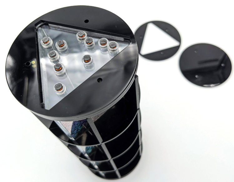
). shows that the LEDs facing upwards, with coils parallel to the transmitter, light up, but the LEDs whose coils are perpendicular to the transmitter may light up only slightly or not at all.
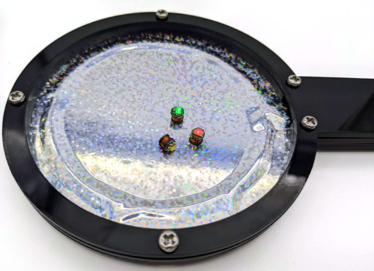
 ). Be sure that you’ve removed any protective paper from the acrylic rings before carefully slipping the LEDs into them. The LEDs should slide easily into the rings. Do not apply pressure to force them in. If the rings seem too small for your LEDs, laser cut another set of rings with a slightly larger inner hole. The LEDs and their collars are easily misplaced, so put them in a small container and set them aside for the moment.
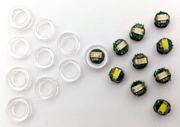
 T). Once all the LEDs have been placed, stack circle D on top of circle C so that the LEDs sit inside the triangular holes in both layers C and D. Next, place circle E on top of D, lining up the screw holes in all five lettered layers. Reinsert the M3 screws into their holes so the screw heads rest on top of layer E. Secure the screws underneath layer A with the M3 nuts. Now, when you move the kaleidoscope, the LEDs are free to slide around, but their collars keep the LEDs always pointed toward the viewer.