OK, quick physics review: There are six elementary movements a solid object can make in space — one straight-line movement back and forth along each of the three spatial dimensions, and one rotating movement back and forth around each of those lines. More complex motions (like orbiting while spinning) can always be described in terms of these six elementary movements, aka degrees of freedom (DOF) and “axes.” Manufacturers of CNC machines and other robots tend to describe their products with phrases like “4-DOF pick-and-place-robot” and “5-axis waterjet cutting system,” to indicate how many different ways the machine can move its end effector. Thus a “six-axis positioning platform” is basically a mounting bracket you can adjust in all possible ways (within a certain envelope).

TL;DR: This thing lets you move something any way you want.

“Awesome!” you are undoubtedly hopefully saying. “What can I use it for?”

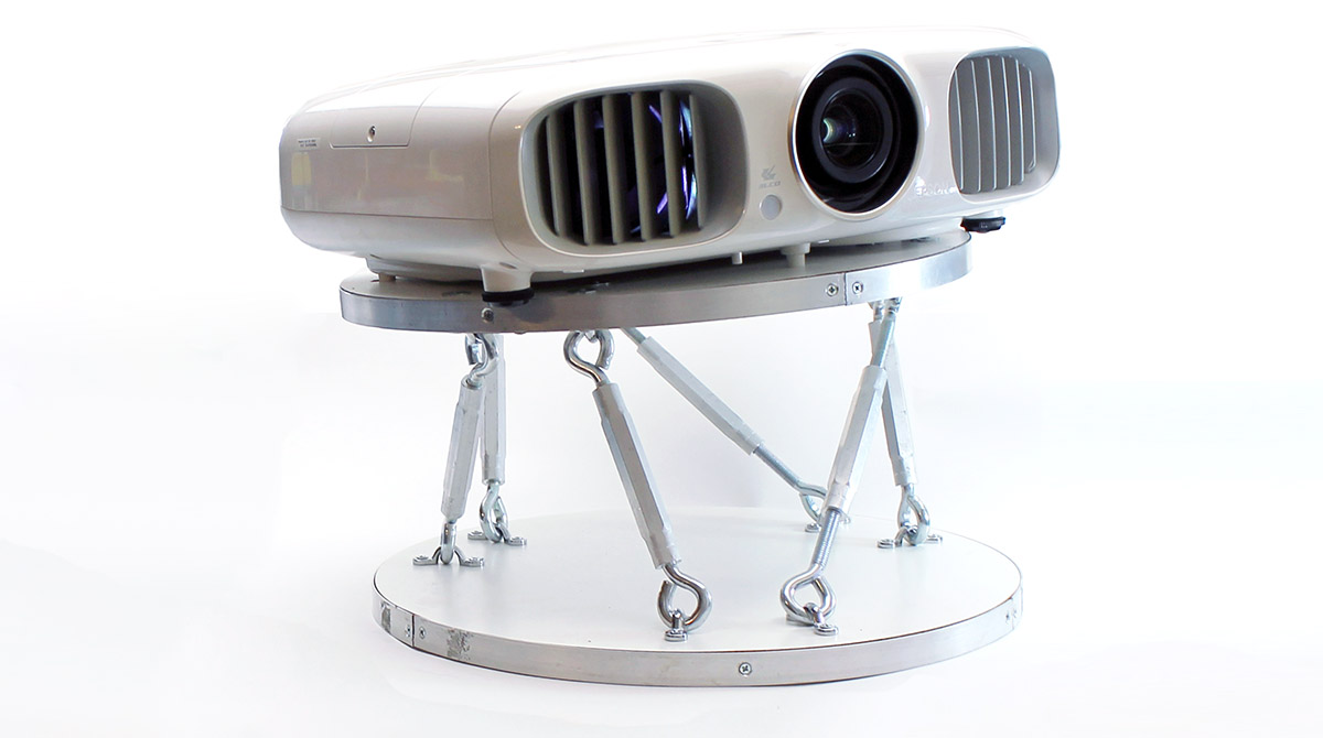
Good question. It’s kind of a solution looking for a problem, really. I used mine to hang a video projector, a task for which it is admittedly overkill. Though it’s nice to have the straight-line movements, it’s the rotational degrees of freedom that truly matter for aiming a projector — and only two of those are indispensable. But it looks cool, right? And I thought the general concept, or maybe just the trick of using turnbuckles as ad-hoc “linear actuators,” might be the apple that fell on some bright reader’s head.

:: sound of tree shaking ::

Project Steps

Step 1.

Cut the circles (OPTIONAL)

You’ll need two of these. Mine are 16″ in diameter, but anything from 15″–20″ should work just fine.

If you don’t want to mess with cutting your own circles, you can just drop fifteen bucks on two of these ready-made edge-glued wooden rounds. They don’t look quite as good to my eye, but the price is right and they will save you the effort both of cutting your own and of finishing the edges.

If you want to do it the harder way, cut two 16″ diameter circles from the melamine panel. I used a manual router with a 1/4″ straight bit and the trusty circle-cutting attachment (aka trammel) I made for it back in 2012. Please refer to my old step-by-step tutorial if you want to make one of these for your own router. You can also just mark a circle with a compass or a tack and a bit of string, then eyeball the cut with a jigsaw.

Step 2.

Attach the drilling templates

Evenly arrange the three templates around the center of the circle at 120 degrees from each other.

Print out three copies of the drilling template PDF at 100% size, then tape them to one of your circles with their center-marks aligned with the center of the circle. (You’ll need to measure and mark this point if you’re using a pre-manufactured round.)

Step 3.

Drill the holes

Drill all the way through both panels to make a total of 24 holes, being careful to hold the drill true as you go.

Carefully align the edges of the two circles and stack them together with the templates on top. (A bit of double-stick carpet tape between the two panels is handy to keep them from slipping out of alignment.) Drill twelve 3/16″ diameter holes through the stack at the points indicated on the templates. Separate the two panels, then remove and discard the tape and templates.

Step 4.

Install the T-nuts

The T-nut side will be at least partly covered by whatever you mount on the platform, so choose the uglier one.

Hammer twelve T-nuts into the holes on one side of one circle. Repeat for one side of the other circle.

Step 5.

Strap down the eyes

If you expect a lot of vibration, use round-head screws with lock and flat washers above the strap holes, instead.

Unscrew the turnbuckle eyes from their threaded bodies. Note that one of them has left-hand screw threads, so you’ll have to turn it the “wrong” way to remove it. Gather all six eyes with left-hand threads and use the straps to secure them to one of the two circular panels with screws through the mounting holes and into the T-nuts on the other side. Repeat this process for the other panel, using the remaining six eyes (i.e. those with standard right-hand threads).

Step 6.

Turn the buckles

If you strap all the reverse-threaded eyes to the same circle, these will all tighten in the same direction.

Align the two panels rotated 60 degrees relative to another, with the eyes between them, and then work your way around the circle threading the turnbuckle bodies back onto the eyes in zig-zag fashion, as shown. Tighten them about halfway to start.

Step 7.

Add edging (OPTIONAL)

If you cut your own panels, you might want to apply strip aluminum, edging tape, or some other edge-treatment at this point, just for the sake of appearances. A better time to do this might be right after cutting them, immediately before Step 2. I waited until the end on the principle that finishing should be added last to avoid messing it up during construction, but the trade-off is that doing so is quite a bit clumsier now that the whole thing is assembled. Use your own judgment.

USE IT

The platform works just as well under tension as in compression.

Drill holes in one panel as needed to fit your projector or other load, and in the other panel as needed to fit your ceiling or other mounting surface (if you want to hard-mount the thing). Secure both panels by passing screws or bolts through these holes and into your load and/or mounting surface, remembering to use a lock washer and flat washer under each one if you expect much mechanical vibration.

Once everything’s mounted, you can get a feel for how to manipulate the turnbuckles to find the position you want by playing around with them a bit. If you want to get math-y about it, you’re in for a pretty deep dive, so I encourage the “try and see” method. Think of the position where all the turnbuckles are as tight/short as they can get as “home.” Start from there.


Terminology fine print: Robotics buffs may recognize this device as a Stewart platform, or something very like one. I’ve avoided using that name A) because eponyms usually make for bad headlines, and B) I’m not sure it actually applies to an unpowered device that has to be adjusted by hand. This is basically the same reason I favor scare quotes around actuators when describing turnbuckles — if you want to argue that a manually-driven screw is not an “actuator” in any useful sense of the word, I’m not about to disagree. (Homework problem: is there an easy way to hack a turnbuckle into a proper linear actuator?) Finally, I’ve shied away from “kinematic” here, again because A) it’s esoteric and B) probably not strictly correct. Though the platform is rock-solid under continuous tension or compression, there is a bit of “wobble” in shifting from one to the other because of play between the turnbuckle eyes and straps.