It started as a bet: The “Phantom of the Floppera” video was making the rounds at work and a co-worker was sure that the video was fake.
“They just dubbed audio over a video of some old computer,” he said.
“Nonsense,” I said. “It’s not even that hard! I bet I could go home tonight and do it!”
After many hours and a lot of trial and error, my salvaged floppy drive eked out the first few bars of “Ode to Joy,” only a little bit out of tune.
Floppy disks have several “tracks” of information on their circular media, and the drives that read them have a head that can step one track at a time across their surface. The position of the head is controlled by a stepper motor, and floppy drives have a convenient interface that moves the head one track at a time with a signal pulse to the right pin. Pulse this signal at a specific frequency and the drive’s vibrations give off sound like a speaker driven by a square wave.
After getting a glimpse of the potential musical floppy drives had to offer, I dug out an Arduino, mooched a grocery bag full of floppy drives off a friend, and set to work making beautiful (or at least recognizable) music. The result? A Java application and Arduino sketch that, as this article will show you, can be used to make floppy drives sing.
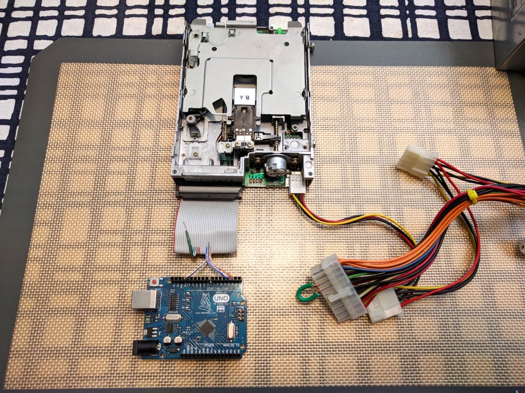
First you’ll need your Arduino, floppy drive(s), power supply, and the floppy drive ribbon cable or jumper wires.
If you’re using a ribbon cable, cut off one end of the cable leaving enough cable to work with (some cables have a twist in them; avoid the twist side to make it easier to follow the wires).
The floppy drive pins are arranged in pairs: odd pins are grounded and even are data. Signals are sent to the data pins by grounding them. There are three data pins that we’re interested in:
12 (or 14) — The “Drive Select B (or A)” pin
18 — The “Direction” pin
20 — The “Step” pin
The Drive Select pin is used to activate the drive so it will respond to signals. When the drive is powered and activated, its LED indicator will light up. The Direction pin determines if the drive’s head moves forward or backward. And each time the Step pin transitions from ungrounded (floating or at 5V) to grounded, the drive will move the head one step in the direction of travel.
If you’re using a ribbon cable, separate the wires; if you’re using jumper wires, connect them to the pins on the floppy drive directly. The Drive Select wire should be connected to its matching ground (either 12–11 or 14–13). Some drives will work with either pair connected, but some will only work with one or the other, so you may need to experiment with your drive to find out which pair of connected pins causes the LED on the drive to turn on (in these photos it’s 12–11).
The Step wire should be connected to pin 2 on the Arduino, the Direction wire to pin 3, and it’s very important that one of the grounded wires is connected to a GND pin on the Arduino (without this, the Arduino and drive may disagree on “grounded” and signaling may not work).
If you have more than one floppy drive, the additional drives’ Step wires should be connected to the even-numbered Arduino pins (up through A2 for eight drives), and the Direction wires should be connected to odd pins (up through A3).
Once the drive is wired to your Arduino, it’s time to attach the power supply. If you’re using an ATX power supply, use the Molex-type floppy drive connector; if you’re using a 5V power supply, the rightmost pin on the floppy drive’s power connector should be +5V and the second-rightmost should be ground (the red wire on the standard power connector is +5V, the black is ground). If you’re using an ATX power supply, you’ll also need to short the green and black wires on the large connector to signal the power supply to turn on.
Once powered, the drive’s LED should light. If it doesn’t, verify your wiring and try switching between the A and B Drive Select pins.
Download and install the Arduino IDE. Open it up and go to Sketch → Include Library → Manage Libraries, and search for and install the TimerOne library. Close the Arduino IDE and plug your Arduino Uno into your computer’s USB port. It may take a moment for the drivers to initialize, but installing the Arduino IDE should have taken care of driver installation as well.
Download the MoppyArduino zip file from Github, unzip it somewhere convenient, and open the Moppy.ino sketch file in the Arduino IDE. The IDE should have automatically detected that you have your Arduino plugged in, but if not you may need to select the appropriate board type and port in the Tools menu.
Click the Upload button at the top of the IDE. The IDE should successfully compile and upload the sketch to your Arduino. Pay close attention to the black console at the bottom of the window to make sure that there are no errors in red text.
If the upload was successful and your power supply is on, the first floppy drive you connected should play a little four-note startup sound anytime the Arduino is reset.
Now download the MoppyControlGUI zip file from the same GitHub page, unzip it somewhere convenient, and run the appropriate MoppyControlGUI executable from the bin folder (e.g. *.bat if you’re on Windows). Select the checkbox under Network Bridges that corresponds to the serial port your Arduino is associated with; the Arduino should reset and will display as a device on the right side of the window.
Click “Load File” to load one of the included MIDIs from the samplesongs folder, then press the play button!
Now that you’ve got at least one musical floppy drive, consider adding more to your orchestra! Try mounting your drives on something aesthetically or acoustically pleasing (maybe with some RGB LEDs). Play around a bit with different mapping settings in the lower section of the MoppyControlGUI application, and try looking for some additional MIDI files on the internet to play.
If you’re feeling especially crafty, this setup is adaptable for playing other stepper motor devices, or playing relays, for a computer-hardware percussion section. The software is all open source too, so any customizations are only a fork away.
Our websites use cookies to improve your browsing experience. Some of these are essential for the basic functionalities of our websites. In addition, we use third-party cookies to help us analyze and understand usage. These will be stored in your browser only with your consent and you have the option to opt-out. Your choice here will be recorded for all Make.co Websites.
Allow Non-Necessary Cookies
Escape to an island of imagination + innovation as Maker Faire Bay Area returns for its 15th iteration!
Buy Tickets today! SAVE 15% and lock-in your preferred date(s).